How a Heart Rate Sensor Measures the Pulse rate?
As we know what we are going to do, so let’s start working on this project.
Step 1: Collecting the Components
Making a list of components and studying the working of those components is the best approach before starting any project. Following are the components that will be used in our project:
Step 2: Knowing the Components Used
As we have the list of apparatus that we are going to use. Now let us see how these components work. Arduino Uno is a microcontroller board that is used to control various circuits. It uses a C code that gives it the instructions to perform a task. Other substitutes of this microcontroller board available in the market are Arduino Nano, Node MCU, ESP32, etc. SEN-11574 is a plug and play pulse rate sensor that is integrated with Arduino. It has two sides. On one side, a led is placed which emits light. This led should be placed directly on the top of a vein. As we know that the volume of blood in the vein is greater when the heart pumps, so when there is more blood in the vein, more light will be reflected to the sensor. This change in the light received by the sensor is analyzed over time and the heart rate is measured. On the other side of the sensor, a circuit is present which is responsible for the amplification and noise removing of the received signal.
Step 3: Assembling the components
All the apparatus is now set and ready to be used. We will put the sensor directly on the vein, either on the finger or the ear to measure the heart rate.
Step 4: Getting Started with Arduino
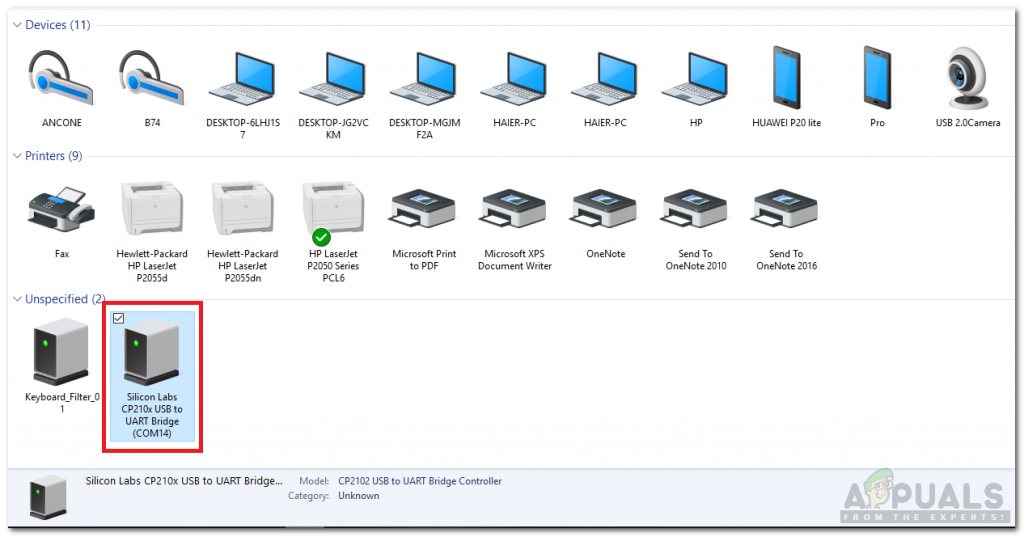
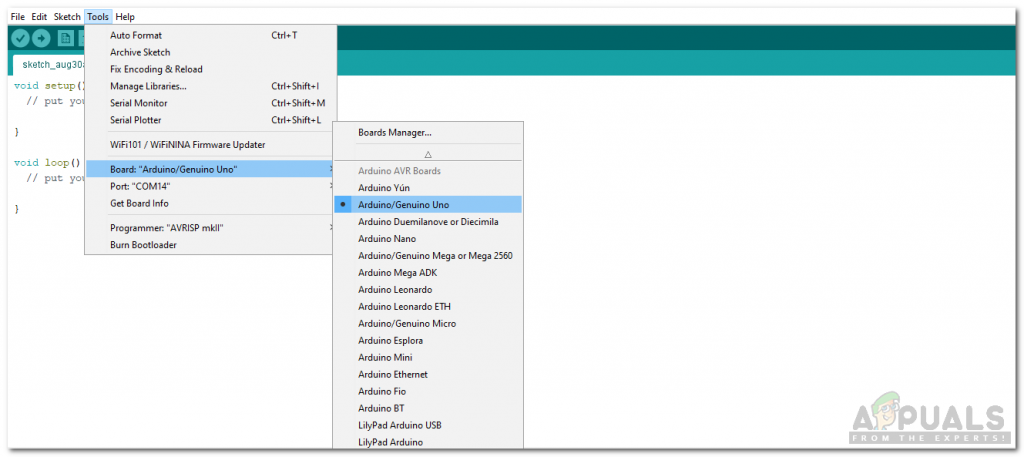
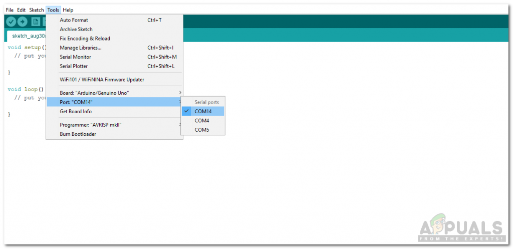
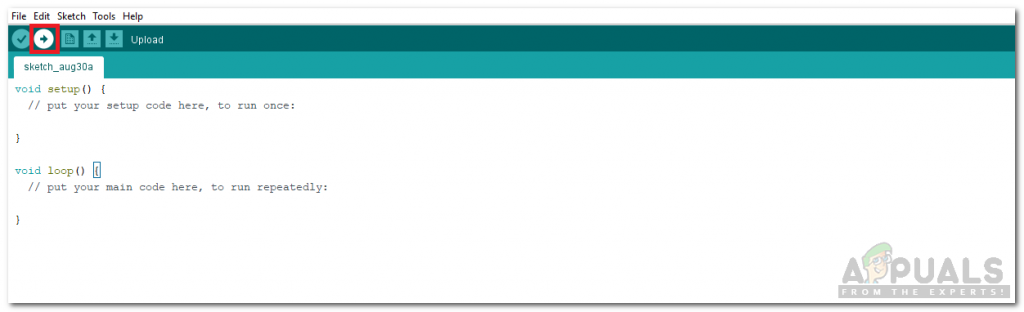
If you haven’t worked on Arduino IDE before, don’t worry because the procedure to burn a code on the microcontroller board using Arduino IDE is given below. Click here to download the code.
Step 5: Code
The code to measure the pulse rate is a little bit lengthy and complicated. Some part of the code is explained below.
- In the start, all the pins that will be used are defined. All the variables that will be used in different functions and the interrupt service routine (ISR).
- void setup() is a function in which Pins are defined to be used as INPUT or OUTPUT. baud rate is also set in this function. Baud rate is the speed by which the microcontroller communicates with other components. ISR is also called in this function.
- void loop() is a function that runs continuously in a cycle. Here, pulse rate is found and it decides when to fade the led when a heartbeat is found.
- void serialOutput() is a function which decides how to show output on the serial monitor.
- ISR is an interrupt that is generated by the hardware and sent to the CPU for processing. when the interrupt is generated, the process, which is already going on stops and the interrupt is processed. after the interrupt is processed, the previous process resumes.
Applications:
Now as we know how to measure the Pulse rate using a heart rate sensor. Now we can use it to make different projects for example
How To Measure Distance Between Two Points Using Arduino?How to Monitor Availability and Measure Latency of Devices on your Network in…How To Make A Floor Cleaning Robot Using Ultrasonic Sensor?How To Detect Rainfall Using Rain Sensor?